electronics - *All Girls Join In*

Annubis

Tokyo and Beyond
Joined
30 Nov 2007
Messages
212
Reaction score
12
With Goldiegirl's inspiration, I am opening this thread for anyone who wants to learn some basic electronics. In this thread we will use a CMOS 555 digital clock to make LEDs flash and Make funny noises with speakers.

Most of the components that we will use can be found at your local Radio Shack or electronics store. I will also post links to other local electronic parts stores and good online electronic shops.

I will try to post new instructions and links every weekend, but forgive me if you don't hear from me for a while. I am a very busy woman! Hehe

Also, please feel free to visit Electronics and robo bits

See you soon
 
Interesting. My father was an electronical engineer, and I never devloped any interest in it...although he tried. (I simply do not know why, but anyway....) Then, for some strange--perhaps only because we don't exactly know why or how such things occur--my eldest son had some natual born knack for such, and started making things in 5th grade that surprized his teacher at school. (because they had not done any lessons on electronics at that time)

So, my father sent him a couple of those Radio Shack sets. We still have one here at house--although my eldest son will be entering a tech school from April in the Machida area. My other two sons don't seem to be interested in electronics.

And IT IS GREAT to see more females working in this area !! Goldiegirl san, have fun and learn a lot !! Those kits are very informative.
 
Guidelines of this thread

First of all, this is not a kit that you can buy. The components have all been selected individually by me.
Second, I will post website sources for electronics and robotics in this thread:
(Electronics and Robo bits) Electronics and robo bits
If you would like to read up on the more detailed specifics for each component being used in our project, please refer to the above thread (Post #8)
Finaly, any critiques or opinions should also be made in the above thread. Only technical questions and comments souly regarding our project should be posted here.
Thank you:p
 
Last edited:
A bit of research before beginning

Study these images:
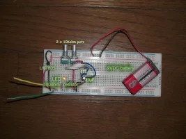
bread555prime.webp
This is the end product of your test circuit.

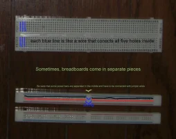
breadboard.webp
You need to start with a bread board which can be put together like a puzzle.

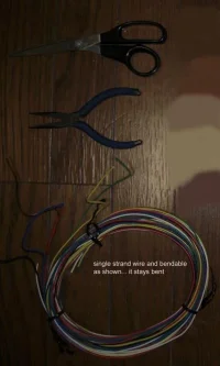
wire and tools.webp
Cutting and stripping wires is tedious, but necessary... if you get a wire stripper, your at an advantage. I usually just use scissors to strip my wires.

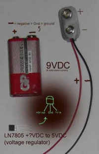
Power.webp
Power is omportant: There will be power details in the link provided in the next post.

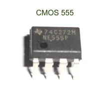
555mod.webp
Here is the brain and the name of the game :)
ref:
when choosing your 555 chip
Whats the difference between a 8-Dip and a 8-SOIC package?
 
Study and find

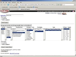
Right... and here's how to choose the 555 chip at Digikey:
search of 555.webp

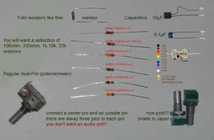
And here are the components you will need:
componentmod.webp
Note: Pots are recomended at 10Kohms, but higher is nicer.

Reffer to this site for details about these components:
Basics
How to Build a Robot Tutorials - Society of Robots

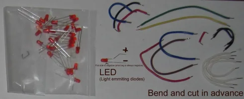
And the great and wonderful LED - Let there be light!
diode and bend.webp


my yellow friend.webp
my long time artist friend - currently in Toronto
 
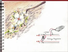
5VDCherry

I won't be able to upload many photos... it seems, but here's one for the power!

Let the water flow! Take your time, and please visit those links. Don't let the undertow of overloaded info take you away!
 

Attachments

  • 5voltDCherry.webp
    5voltDCherry.webp
    118.5 KB · Views: 187
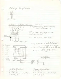
Schematic for the CMOS 555

How is it going? Have you been able to find any of the components? If you need any tips or help. Please feel free to ask!

I come to JREF often and am excited that there may be others interested in this very simple project. It is quite rewarding to see that LED flash after all of your effort. Ganbatteyo!

Here is an update... perhaps the last attachment for a while. This is the schematic for the gogogo (555) chip.

Take care and have a happy golden week! Please stay healthy. Take your vitamines and exercise. Rest and laugh. Don't let life get you down!🙂
 

Attachments

  • schematic.webp
    schematic.webp
    30.6 KB · Views: 179
Simply 555

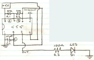
I realized that the attachment I gave you was a bit too complicated and not very clear. So here's a better one... hehe... just a blown up section of the one above. The 555 chip is to be placed at the centre of the bread board with each pin in it's own hole. Please refer to the above links and attachments.

Pin 1 is always on the bottom left corner of the chip. if you look at the picture of the 555 above and the chematic I have provided. You will notice the half moon shape or the circle on the left. that is to show the proper orientation. Pin #1 is always on the side of the circle or half moon :)

Also you will notice a plus symbol on the capacitor's symbol -)l- in my schematic. That is to let you know that the line ( l ) in the symbol for the capacitor represent's where the positive (long) pin should go. The line for an LED ->l- represents where the negative (short) pin should go. And the /\/\/\ is the symbol for the resistor. A resistor can be place which ever way.
 

Attachments

  • schematicsimple.webp
    schematicsimple.webp
    44.6 KB · Views: 170
Last edited:
Back
Top Bottom